
Requires 3x power nodes
It seems to be an all too common introduction to my posts lately; "Well, It's long over due, but it's finally complete". I hinted last year that I was working on a larger project; that one eventually never made it off the design table for specific reasons but morphed into this project. I have a very brief post on what the project was going to be here, but I won't dwell too much on that in this post.
This project is going back to a franchise I really enjoyed; Dead Space. Previously I made the rig helmet for a friends birthday but I wanted something for myself too. Since making the rig helmet I've learned a fair amount about 3D printing so I was ready for setting myself a challenge a bar higher. So I thought it's time to delve into combining 3D printing with some electronics. I eventually settled on the Dead Space bench, it covered what I was looking for; something from the franchise, has some interesting moving parts and I can add a display module as well to help ground it more as the bench from the game.
YouTube Video
As normal, I'll start with an embedded Youtube video. This video doesn't go into the full details of the project but does contain some of the all important footage of the final results.
Planning
A lot of my projects tend to start out with just a very basic concept of how I'm going to do things and a basic sketch. I don't tend to spend too much time on the planning side as 3D modelling allows you to make adjustments as you go, I just need a very basic plan and then dive straight into it. This project however I had to make more than just the basic plan before starting as it would involve electronics and movement. So I spent a little time going over what the bench roughly moved like in the game and then figured out how to make this happen with a physical object as best as I could. Game objects that move sometimes "cheat" (I use that term loosely) in that they either wouldn't be able to function like that in the real work and clip through things in the virtual game world. These days items are becoming more realistic in this area, but some "cheating" still happens.

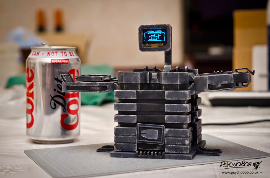
The bench in the game moves up vertically exposing some segment sections in the "central column" area and then the main side "trays" swing down from the vertically standing state to the horizontal state in which they can be used to put items on. The holographic interface then expands to fill the screen and then gives you the various options for the bench in the game.
I could mimic the movement and I could see how I could do it with a single servo, so that made things much easier as this would be a small scale bench. The hologram unfortunately was something I obviously wouldn't be able to replicate, but I could at least have a small display screen to mimic some of the functionality. I went for a small OLED module in the end as it was affordable and would cover the basic needs (if I had unlimited funds I could have gone for something like the 4DS transparent OLED which is bigger and as the name implies, transparent; further selling the idea the interface is holographic). The OLED module needs a microprocessor to control what is displayed and as I was going to have to have a microprocessor, I also decided to use it to control the servo. After some research, there seemed to be two popular choices to go with; PIC or Arduino. I eventually settled on the Arduino, or more specifically the Arduino Uno R3 board.
I then had a quick think about the power source and as normal, I wanted to avoid batteries. I generally like powering things through a USB on a PC but this project involved a motor which can draw a lot of current causing damage to the PC port. However in this day an age, we have those handy USB AC mains plugs for your smart phones or tablets so I could stick with the USB idea. The plug for my tablet covered up to 2.5A, plenty for what the circuit should draw. One final improvement over my other projects I wanted to incorporate was not to have the USB cable permanently attached to the project. So I decided I would attach a female micro USB port so I can disconnect the cable and put the piece on the shelf when not in use.
Lastly I thought about how you would actually initiate these actions via buttons. At first I was going to mount some buttons to the base plate but then I noticed the logo panels on the front and sides of the bench's central column. This was perfect. Three logo panels that I could use as buttons; one to activate the bench and then two to cycle through the screens.
So that was the basic planning done, time to get to it!
Making the 3D model
In reality I actually worked on the 3D model and the electronics in tandem as the circuit components size would affect the 3D model parts, but it's a bit hard to write about them both at the same time so I'm going to split them apart. For the modelling process, I used Solidworks (I seem to be using CAD quite a lot these days for 3D printing, but still use Modo in the process every now and then, especially if I'm playing around with the model design as it's much more fluid to do that in Modo) which has some useful tools such as collision detection so I could simulate the moving parts to see if they collide in undesired situations.
The original model was going to use a timing belt in order to give the OLED screen some back and forth movement when the bench activates. However I couldn't easily find a belt of the right size or price for my needs! It was unfortunate, but I changed the design so the OLED module was affixed to the central tray.
I had the basic model done but then went on to completely finish the electronics before continuing so I could ensure the model would be able to house things. I'll get to the electronics in a moment, but once they were completed I finished up the model, made a few modifications along the way so they would fit properly and then the model was complete. When making the model I designed it so it could be taken apart, so I modelled press fittings and screw holes so it could be taken apart relatively easily if I needed to (i.e. if the servo ever stopped working or found bugs in my code so I could update the microprocessor code). The model isn't 100% accurate (for instance there are 3 upper blocks in the central column when I believe there are only two in the game, the screen is being suspended via a "pipe" whilst in the game this hovers as a holographic interface). I decided to hollow out the cylinder component of the right hand side tray as I had some Milliput (two part putty) spare from another project, so I saved a little money on the 3D print this way. I also had some styrene, so I decided to make some of the inner mechanism parts with that rather than 3D print them (3D printing via third parties isn't cheap! So I save where I can).

Electronics
Prototyping


Using a few breadboards I started getting to work on the circuit. I started with the servo as that seemed to be the most straight part to get working. I made a basic circuit which would allow me to power the servo from a dedicated power source for the development stage (in this case 4x AA batteries) but send the control signal from the Arduino. Whilst the Arduino is capable of sending enough power for a servo, it's generally not a good idea to power something like a motor directly off it's pins as it can damage the board or components because the current a motor can draw. That's why I used batteries during development to isolate it. I connected a basic push button to the circuit, added in some code and then I had a fairly basic circuit that would turn the servo to one position when the button was pressed and to another when pressed again. This is the basic control mechanism for activating and deactivating the bench.
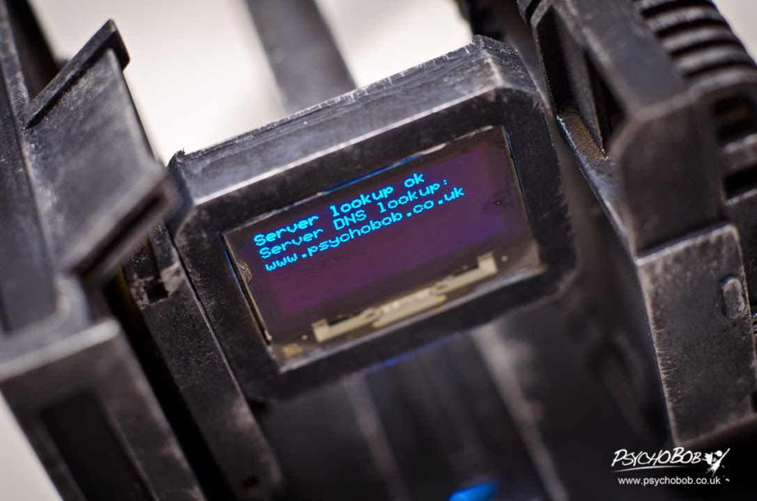
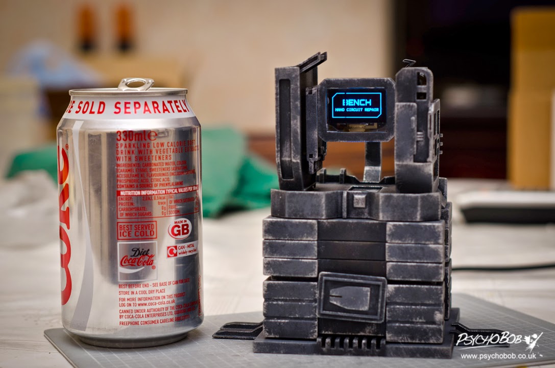
From here the circuit began to grow. I added in the components for the OLED module, it drew very low current and the voltage requirements was only 3.3v. I loaded up a demo code example to make sure I had the OLED connected properly and then from there I began writing the code to make the screen output what I wanted. I wanted to go through a faux "boot" sequence (that would have a shameless plug for my website), then I would need it to wait on the "nano circuit repair" screen until the activate button was pressed. When pressed the servo would activate and then you would be taken to the inventory screen. Two additional buttons were added to the circuit and when pressed they would then allow you to cycle back or forth through the available "circuit" screens.
The OLED pixels only have an "on" or "off" state, no opacity controls so the screens I was making couldn't completely replicate the ones from the games. I originally had horizontal scanlines, but without opacity control they added too much "noise" obscuring much of the information, so I decided to omit those. Once the basic OLED functionality was there it was time to add on some bells and whistles. I wrote some extra code functions that would make a vertical "scanline" scroll horizontally on the screen whenever it was idle. As the OLED pixels only have an "on" or "off" state, I was having to update the entire screen quite regularly. Not a problem, but on some of the more complicated screens (i.e. the inventory screen) you can notice it moves slower than on others because of the amount of data it's updating on each move of the scanline. I also added in the bench logo screen complete with blink effect from the game, and I added an animation to the exit status of any of the screens to make the transitions less abrupt and more interesting.
I finally added in some additional code to prevent the bench getting stuck in "odd" states. I wrote some code to reset it's position when powered on during the boot up phase (should the bench ever be activated and then have the power removed for instance), prevented the buttons from working until the boot sequence had finished, prevent the next/previous screen buttons from working until the bench was activated etc... These aren't necessarily needed but it's good practice to try and prevent any undesired situations with code enforcement. In the end the arduino code came to just over one thousand lines of code.
The Arduino Uno board is quite compact, but it is a development board at the end of the day so it has a lot of extras that you don't necessarily need in every project. You may not need all the digital/analog pins, the voltage outputs, the USB port, the DC jack etc... A lot of people I find tend to put the entire board into the projects permanently, not because they need everything but just because it's the easiest thing to do (I personally think it isn't the most economical thing to do either as you need to replace the entire board if you have another project). I didn't want to follow their example as it's just a waste and wanted to only use the Uno board as the development platform. So I removed the microprocessor, bought the parts I needed to run the chip (a 16Mhz crystal, a few capacitors and a few other bits) and then I could run everything without the board. The parts are inexpensive and it means I can just spend a few pounds replacing the chip so I can use the Uno board again (it's certainly cheaper than just replacing the board all the time). It also means I don't have to add space for the Arduino board which has a bigger form factor than what I could make as I didn't need all of it's features. For anyone looking to do the same, I used the schematic from breaduino to figure it out what components I needed (a lot of it I already had, I just needed a few additional parts like voltage regulators).
Finally I hooked up the female micro USB port to the breadboard with a voltage regulator and I had my circuit working without the Uno board. The micro USB was pretty difficult to solder wire to; the pins are microscopic! I eventually did this but I burned out the first USB port I tried, luckily I had a second one. I finally used some heat shrink to help protect the joint so if it ever gets pulled on, the heat shrink should take the brunt rather than the weak solder joint. I did this to all my wiring as it's just good practice if you have the option.
Shrinking and finalising


The breadboard ptototype circuit was pretty bulky and messy. For it to fit into the bench, I would need to shrink it and that's where strip board (or vero board) normally come into play. This generally shrinks things quite considerably as you use the copper tracks to replace some wiring. However the circuit was quite complicated and I would have to stack multiple layers of the strip board to make it work. So I looked into the PCB route and eventually went down that path. I found a place that would make custom PCBs and I was a bit sceptical as they provided a pretty cheap service, but took a shot as they accepted paypal (if anything went wrong). So I created my circuit schematic in a piece of software called Eagle, created the board layout and then sent it to them for them to produce.
It came out beautifully! As they were based half way around the world, I had to wait 3 weeks but I then got the boards in the post. They provided me with 5 copies of the board (minimum you need to order with them) and they all seems to work. I used the continuity setting on my multimeter to test the board and it all seemed to match up to the schematic I sent them so they did exactly what I wanted them to do
I soldered all the components to the board (the crystal, capacitors, resistors, headers etc...), put in the micro processor and then bam! ... nothing worked. At first I thought I made a cold solder joint but they all seemed to be fine. After a few hours of tearing out my hair, I eventually found the issue. On the breadboard prototype everything was good, however when I created the schematic I put the capacitors on the wrong side of the crystal. With some extra wire and stripboard, I made a fix for the PCB board. It's a bit bulkier and looks messier, but it worked and I was up and running. Aside from that mistake on my part, everything was good with the circuit!
Post process after printing
Modifying and smoothing out the parts


Once I uploaded the model file for printing and received the parts, I cleaned up the parts as usual to remove any loose powder from the SLS process. Before getting to the smoothing stage, I tend started adding the internal styrene pieces (braces and parts to keep the parts inline and prevent slippage when they move). Styrene is cheap, very malleable and easy to work with. I also adding in the milliput into the hollow cylinder and shaped it to have a rounded top. The reason I did this before the main smoothing stage is because I use filler putty in the process and that could help stop the styrene or miliiput bonding to the plastic properly if they are attached after the filler putty has gone down.
Once that was done, I then went through the usual tedious sanding stages. As always, very repetitive, very time consuming and it tends to be pretty boring! If you hadn't gathered it yet, this is always my least favourite part of the process.
I also felt that the model was a bit too light and was wobbling when the servo activates, so I sealed some 2p coins in the base with some milliput in order to give the base some more weight. This stopped the wobbling.
Attaching the permanent pieces
As mentioned previously, I designed the part to have press fittings and screws where possible so it would be easy to disassemble if needed (for instance if a servo stopped working). However a few parts did need to be permanently attached to one another. That was the OLED "casing" and the pipe that connected the casing to main central tray. So I had to wire up the OLED screen and then seal it into the casing prior to painting. I then used some white-tac over the screen to prevent the paint sticking to it and some cling film to protect the wiring from the paint. I also decided at this stage to add some hotglue to prevent the OLED wiring inside the piece from getting caught on any moving parts.

I superglued the push switches to the panels that would act as buttons and then covered them in cling film to protect them. They had headers attached to them making it easy to attach/detach them from the main circuit. As the buttons were circular, this unfortunatley mean they could rotate. I didn't discover this until the very end so I had to go with it, but an improvement would have been to use square buttons so they wouldn't rotate. That or circular push buttons that don't rotate! You will probably notice this in the video when I push the buttons they can rotate. This wasn't intentional.
I used some brass tubing to act as the hinge for the two side trays and before supergluing this into place, I added some 3-in-1 oil to ensure it smoothly rotated. It probably didn't need this but I thought why not add a drop just in case! With this, all the hard work was out of the way and it was time to get painting.
Painting

The painting was fairly typical and I can't really say too much about it I've never said before. I used an airbrush to apply some acrylic paints, I then used some silver paint to dry brush on fresh metal damage. Finally, I sealed everything with some clear coat and the part was finally ready for assembly (once I removed the white-tac and cling film I used to temporarily protect things from the paint that is).
Putting it all together
Time for the final assembly. All the parts went together pretty nicely, there were no issues. It was a little difficult getting all the header pins from the switches, LED, micro USB and OLED screen connected to the circuit (as it was done in a very tight space), but that's where a trusty pair of tweezers come into play. They made light work of this and everything connected up great.
I finally screwed the base down and I had my finished piece!


That is amazing and it looks absolutely fabulous. May I ask where you found the OLED screen and how much you paid for it?
ReplyDeleteI bought the OLED module off eBay, but it seems to have unfortunately been discontinued when I last checked. It was cheaper than my expectations (under £15 including VAT and shipping), it just took some to ship as it came from Hong Kong.
DeleteNot a stupid question at all! At this point in time, I'm afraid I don't have any plans to make any more of these. If there's enough interest I may re-consider and should EA/Visceral not object when I contact them (after all this is based off their design).
ReplyDeleteThanks for visiting my website and leaving a comment, I always appreciate people taking the time to visit it. This is actually the first comment since I re-designed it a few days ago so I'm glad I didn't break the comment system or make it too obscure to find!
shut up and take my money :p
ReplyDeleteseriously, if you DO ever decide to try to sell these, I'll be one of the first to order :D
would definitely buy. great work.
ReplyDelete